Experiment Two
Statics FE Analysis for Plane Structure
A. Purposes of Experiment
a. Grasp geometric body constitution method, meshing method, theenforcementof boundary condition method and various load enforcement method of ANSYS software.
b. Be familiar with the finite element modeling, solving , procedure and method of result analysis.
c. Can use ANSYS software tocarry through statics analysis for plane structure.
B. Experiment Equipments:
Computer,ANSYS software(education version)
C. Experiment Contents:
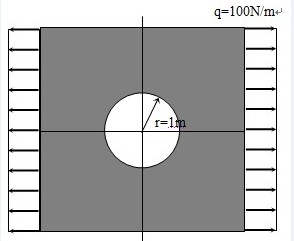
As the figure shown,use ANSYS to analyze the flat with hole, and to analyze stress distribution insidethe flat under the impact of uniform load.
Known conditions:
q=100N/m,length of flat L=12m,width b=12m,thick t=0.02m ,radius of circular hole r=1m,modulus of elasticity of flat E=2.06×10¹¹Mpa, poisson ratio v= 0.3.
D. Experiment Procedures:
a.Analyze problem:
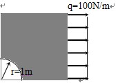
Analyze a quarter of the mode because the mode and constraint load are symmetric.
a. Finite element modeling:
(a). Set up working file and add title;
In ANSYS working directory build a file named plate in order to save files produced in analytical process.
After running ANSYS, make the working directory to file named plate by using menu ‘File’--‘Change Directory…’; make files produced in analytical process to plate for prefix by using ‘Change Jobname…’ and inputting beam as the initial file name.
Select structure analysis, operate as follows:
GUI: Main Menu > Preferences > Structural
(b). Select element;
First, enter into element type library, operate as follows:
GUI: Main Menu > Preprocessor > Element Type > Add/Edit/Delete > Add…
In the dialog box select the Solid option left, select the Quad 8 node 82 option in the right list, then click OK button.
Because this problem adopts element type of plane stress analysis with width, analysis type is Plane strs w/thk. operate as follows:
GUI:PreProcessor Menu > Element Type > Add/Edit/Delete > Options…
Select ‘Plane strs w/thk’ in the pull-down menu behind K3 option.
(c).Define real constant;
Define real constant according to element type, operate as follows:
GUI: Main Menu > Preprocessor > Real Constants > Add/Edit/Delete >Add…
In this example, element width is 0.02m.input 0.02 in textbox behind THK in the popping dialog box.
(d). Define material property;
Operate as follows:
GUI: Main Menu > Preprocessor > Material Props > Material Models > Structural > Linear > Elastic > Isotropic
Input material parameter in the dialog box showed: Young’s modulus (EX):2.06e11
Poisson Ratio (PRXY): 0.3
(e) Build solid model;
We can only build a quarter of the mode, because the geometric mode , material parameter and load are symmetric for level and vertical centre line. Build the quarter of above mode by making hole core be origin of coordinate. First, plate is created by length and width. Then we can get the figure by subtracting the quarter of circle.
① Create rectangle:
Define rectangle by length and width, operate as follows:
GUI: Main Menu > Preprocessor > Modeling > Create > Areas > Rectangle > By 2 corners
Input origin of coordinate (0,0), length 6 and width 6 in the popping dialog box.
② Create circle:
Operate as follows::GUI: Main Menu > Preprocessor > Modeling > Create > Areas > Circle > Solid Circle
Input origin of coordinate (0,0) and radius 2 in the popping dialog box.
③ Subtract the circle from rectangle plate:
Realize the subtracting of face by Boolean, operate as follows:
GUI: Main Menu > Preprocessor > Modeling > Operate > Booleans > Subtract > Areas
Select rectangle, then click OK; select circle, then click OK.
(f). Meshing;
First, enter into MeshTool dialog box, operate as follows:
GUI: Main Menu > Preprocessor > MeshTool
Select ‘Areas’ in pull-down menu of dialog box of ‘Element Attributes’. Pitch up the small box before ‘SmartSize ‘, set the value of SmartSize 6, make the system set the mesh size of each side. Click the button ‘Mesh’, pick up mode, then click OK.
Save date base.
GUI: Toolbar >SAVE_DB
c. Enforce load and solve:
(a)Define constraint;
Because the solid mode and load are symmetric, we can define constraint by symmetry. ANSYS offers special installation in order to set symmetric condition, namely setting ‘symmetry boundary condition’ along the symmetric axis. Operate as follows:
GUI: Main Menu > Preprocessor > Loads > Define Loads > Apply > Structural > Displacement > Symmetry B.C > On Lines
Select bottom margin and left side, click button OK in dialog box. So there is a ‘s’ along the symmetric axis.
(b) Enforce load;
Apply uniform load on the left of plate, operate as follows:
GUI: Main Menu > Preprocessor > Loads > Define Loads > Apply > Structural > Pressure > On Lines
Pop ‘Apply PRES on Lines’ dialog box, then input load value -100, click OK..
(b). Solve;
Operate as follows:
GUI: Main Menu > Solution > Solve > Current LS
d. Check the Analytical result。
(a)Check the deformed and undeformed figures of mode;
GUI: Main Menu > General Postproc > Plot Results > Deformed Shape> Def+undeformed
Save figures by using menu ‘PlotCtrls’> Hardcopy > To file…
(b)Check equivalent stress;
Display equivalent stress contour map, operate as follows:
GUI: Main Menu > General Postproc > Plot Results >Contour Plot > Nodal Solu > Stress > von Mises stress
Then click the button OK. Save figure by using menu ‘PlotCtrls’ > Hardcopy > To file…
(c)Check the animation of deformation process;
Manu PlotCtrls > Animate > Deformed Results > Stress > von Mises SEQV
Then content of animation will be saved as avi format in working directory automatically.
D. Experiment summary:
a. Modeling:
Be familiar with basic modeling operation, grasp Boolean operation, can proceed simple Boolean subtract operation.
b. Enforce load and solve:
Grasp the procedure of defining symmetric constraint and operation of enforcing uniform load ,can judge whether can we simplify mode by its symmetry according to structure and load distribution.
c. Check the analytical result:
Grasp the operation of display of deformation figure and contour map of stress, grasp the operation procedure of displaying the parameter change in animation and can display deformation animation.