Experiment One
Statics FE Analysis for Beam Structure
A: Purpose of Experiment
a. Deepen the understanding of finite element theory related to meshing concepts and meshing principals.
b. Be familiar with the finite element modeling, solving , procedure and method of result analysis.
d. Can use ANSYS software tocarry through statics analysis for simple parts.
B: Experiment Equipment
Computer,ANSYS software(education version).
C: Experiment Content
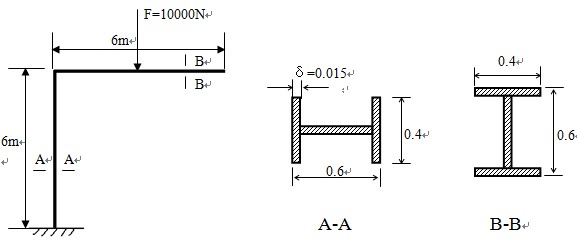
Use ANSYS software carrying through statics analysis for beam composed of I iron and showed in following picture to get the stress distribution.
D: Experiment Procedure
a. Finite Element Modeling
(a) build a working folder:
In the default working directory build a file named beam before running ANSYS software. All files produced in subsequent analytical process will be saved in the above file.
After running the ANSYS, make the working directory to file named beam by using menu ‘File’--‘Change Directory…’; make files produced in analytical process to beam for prefix by using ‘Change Jobname…’ and inputting beam as the initial file name.
Select structure analysis, operate as follows:
GUI: Main Menu > Preferences > Structural
(b) select element:
Operate as follows: GUI: Main Menu > Preprocessor > Element Type > Add/Edit/Delete > Add > Structural Beam >3D 3 node 189
then close the dialog box of Element Types
(c) define material property:
Define modulus of elasticity and poisson ratio, operate as follows:
GUI: Main Menu > Preprocessor > Material Props > Material Models > Structural > linear > Elastic > Isotropic
Input material parameter in the dialog box showed: Young’s modulus(EX):2.06e11
Poisson Ratio(PRXY): 0.3
(d)define the section type and dimension of beam:
Operate as follows: GUI: Main Menu > Preprocessor > Sections > Beam > Common Sections
select the shape of ‘工’,input as follows :W1=W2=0.4,W3=0.6,t1=t2=t3=0.015
(e) build solid model:
First, define three keypoints, then create solid mode of beam by passing the keeypoints. 首operate of define keypoints as follows:
GUI: Main Menu > Preprocessor > Modeling > Create > Keypoints > In Active CS
Coordinate parameters of keypoints as follows:
1#keypoint X=0,Y=0,Z=0
2#keypoint X=0,Y=6,Z=0
3#keypoint X=6,Y=6,Z=0
Create lines as follows:
GUI: Main Menu > Preprocessor > Modeling > Create > Lines > Lines > Straight Line
Create straight lines by connecting keypoints 1 and 2, 2 and 3.
(f)meshing
①First, set the section direction of beam, operate as follows:
GUI: Main Menu > Preprocessor > Meshing > Mesh Attributes > Picked Lines
Pitch up 12 line, then click ‘OK’, choose ‘Yes’ in the option ‘Pick Orientation Keypoint’ of the dialog box, pick point 3 as reference point. Similarly,pitch up 23 line, then choose point 1 as reference point.
②Ten copies of meshing, operate as follows:
GUI: Main Menu > Preprocessor > Meshing > MeshTool > Lines set (input 10 at NDIV) > Mesh
③After meshing, it can be seen clearly by displaying section. operate as follows:
Menu ’Plotctrls’ > Style > Size and Shape … > Opt On of Display of element
Adjust angle by pressing ‘Ctrl’ key and the right mouse button.
④save date base. GUI: Toolbar >SAVE_DB
b. Enforce Load and Solve:
(a)define constraint
Defineconstraint on keypoint 1,operate as follows:
GUI: Main Menu > Solution > Define Loads > Apply > Structural > Displacement > On Keypoints
Select keypoint 1,click ‘OK’ button. Select ‘All DoF’ to restrain all in DOFs to be constrained list, then click ‘OK’. That you will see arrows at the point keypoint 1 means the point has been restrained.
(b) enforce load
Apply download load (Fy=-10000N)on the middle of beam upside, operate as follows:
GUI:Solution > Define Loads > Apply > Structural > Force/ Moment > On Nodes
Pop dialog box of ‘Apply F/M on Nodes’,input -10000 in the place following Fy, then click OK.
(c) solve
GUI:Solution > Solve > Current LS
c. Check the Analytical result:
(a)check the deformed and undeformed figures of mode
GUI: Main Menu > General Postproc > Plot Results > Deformed Shape> Def+undeformed
Save figures by using menu ‘PlotCtrls’ > Hardcopy > To file…
(b)check equivalent stress
Display equivalent stress contour map, operate as follows:
GUI: Main Menu > General Postproc > Plot Results > Nodal Solu > Stress > von Mises stress
Then click the button OK. Save figure by using menu ‘PlotCtrls’> Hardcopy > To file…
(c)check the animation of deformation process
Menu PlotCtrls > Animate > Deformed Results > Stress > von Mises SEQV
Then content of animation will be saved as avi format in working directory automatically.